of geospatial solutions
Sat-Sun: Non-working days
For a long time, the Russian high-resolution Earth observation satellite group was composed of spacecraft initially developed for the needs of the Russian Ministry of Defense. Although some of these satellites were later designated for civilian use, the information obtained from them was not intended for widespread use. The range of departments and organizations allowed access to this data was very limited, and commercial activities were generally minimized. Meanwhile, in the United States and several other countries, effective mechanisms for interaction between the state and the market have been in place for several years. The inability to obtain space imaging data from Russian satellites led various commercial organizations and some Russian state institutions to purchase space imaging materials from foreign suppliers. Hence, the need for creating a proprietary group of commercial satellites has been mature for a long time.
And so, on July 22, 2012, from the Baikonur Cosmodrome, the Soyuz-FG rocket launched two twin Earth observation satellites: the Russian "Kanopus-Vulkan" satellite (hereafter KA "Kanopus-V") and the Belarusian satellite (hereafter BKA). The development and creation of these spacecraft were carried out by the enterprises of FSUE "NPP VNIIEM" and the Scientific and Practical Center for Geoinformatics of the National Academy of Sciences of Belarus, commissioned by the Ministry of Emergency Situations of Russia, Roshydromet, the Ministry of Natural Resources of Russia, the Russian Academy of Sciences, and the National Academy of Sciences of Belarus. Part of the resource of these satellites will be used for commercial purposes.
Characteristics of the "Kanopus-V" and BKA Satellites
Both spacecraft have a similar external appearance, similar characteristics, are equipped with the same imaging equipment, and are in the same sun-synchronous orbit with a separation angle of 180 degrees from each other. They were designed to work in tandem. Figure 1 shows the external appearance of the spacecraft. Table 1 provides the main characteristics of the satellites.

Fig. 1 — External appearance of KA "Kanopus-V" and BKA
Table 1 — Main characteristics of KA "Kanopus-V" and BKA
|
Satellite Size, m×m |
0.9×0.75 |
|
Satellite Mass |
450 kg |
|
Payload Mass, kg |
110 |
|
Orbit: altitude, km inclination, degrees orbital period, min equator crossing time, hours |
Sun-synchronous morning 510 98 94.74 10:30 – 11:00 |
|
Platform: |
from -40° to 40° 5 0.001 |
|
Revisit Period, days |
15 |
|
Average Daily Power, W |
300 |
|
Active Lifespan, years |
5-7 |
The "Kanopus-V" and BKA satellites are designed to address the following tasks:
- Monitoring of emergency situations;
- Cartography;
- Detection of forest fires and emissions of pollutants;
- Registration of anomalous physical phenomena for the study and prediction of earthquakes;
- Monitoring of water resources and agriculture;
- Land use tasks;
- High-cooperative observation.
Currently, the KA "Kanopus-V" is the main Russian high-resolution Earth observation satellite, and its launch signifies the progress in the development of Russian cosmonautics.
Structurally, the "Kanopus-V" and BKA satellites include a service platform (SP) and a payload complex (PC). The structural diagram of these spacecraft, using the KA "Kanopus-V" as an example, is shown in Figure 2.

Fig. 2 — Structural diagram of KA "Kanopus-V"
The service platform is intended for navigation support, spacecraft motion control, and computational operations for spacecraft orientation in space. The SP includes the onboard control complex (OCC) and service systems (SS). The OCC, in turn, includes:
- Onboard computing system (OCS);
- Motion control and navigation system (MCNS);
- Telecommand system (TCS) consisting of: onboard command-measurement system (BCMS) and telemetry observation system (TOS).
The service systems include:
- Power supply system (PSS);
- Thermal control system (TCS);
- Propulsion system (PS).
The payload complex is designed for the collection and formation of video data, followed by transmission via radio channel and includes:
- Measurement (imaging) equipment;
- Data management and formation unit;
- Radio channel for target information transmission (RCTI).
The imaging equipment includes two imaging systems that provide Earth surface imaging and microframe formation:
- Panchromatic imaging system (PIS);
- Multi-zone imaging system (MZIS).
The first system allows obtaining video data of the Earth's surface in a single spectral range (panchromatic), with a high spatial resolution of up to 2.1 m. The second system, in four spectral zones (panchromatic, visible, near and medium IR), provides video data of the Earth's surface with a spatial resolution of up to 10 m in the visible range, 20 m in the near IR, and 40 m in the medium IR.
At the user's request, digital information about the state of the onboard systems, the satellite's orbit parameters, and the equipment installed in the KA "Kanopus-V" and BKA can be obtained through the remote sensing information and the ground control complex (GCC). With the use of the telemetry observation system (TOS), the telemetry data on the state of the spacecraft, such as the temperature of the onboard equipment, the charge of the batteries, and the state of the power supply system, are sent in real time. Through the system of target information transmission (RCTI), digital data on the Earth's surface collected by the PIS and MZIS can be obtained.
Table 3 — Main Characteristics of RSPI
|
Range of operating frequencies, MHz |
8048 - 8381.5 |
|
Number of transmission channels |
2 |
|
Data transmission rate, Mbit/s |
61.4…122.88 |
Dynamic Model of PSS and MSS Imaging
Video information obtained from spacecraft of high and ultra-high resolution contains geometric distortions due to lens distortion, curvature of light rays by the illuminator, internal refraction of light due to atmospheric pressure difference inside and outside the equipment compartment, as well as calibration errors of imaging equipment. Therefore, for high-precision photogrammetric work, it is necessary to model imaging considering geometric distortions.
Currently, there are around a dozen different methods for correcting distortions, but Rational Polynomial Coefficients (RPC) have become the standard for describing and correcting distortions in satellite images. RPC are a set of parameters required to solve third-degree polynomials, which are necessary and sufficient to improve the geolocation accuracy of high and ultra-high resolution satellite video data. They are based on the following relationships linking normalized geodetic coordinates of a ground point with its normalized image coordinates on the photograph:

Numerators and denominators of these relationships are third-degree polynomials:

Normalization of pixel and geodetic coordinates is performed so that their normalized values do not exceed 1 in modulus, and is carried out according to the following formulas:

As can be seen from the equations, the initial parameters required to solve the equations are:
- coefficients of polynomials ;

- normalization parameters: corrections for offset
 and corrections for
different scaling
and corrections for
different scaling 
Coefficients of rational functions are calculated as follows:
- Elements of external orientation of the photograph are determined in accordance with a strict sensor model based on reference points (or external orientation elements obtained from navigation data);
- Anchor points (xf, yf, X, Y, Z) are uniformly calculated across the entire field of view and the entire height range of the area using a strict sensor model;
- A system of equations is formulated, and the coefficients of rational polynomials are calculated using the method of least squares (MLS).
It is important to know that having correct RPC, which accurately describe the sensor imaging model, allows photogrammetric work to be carried out without additional refinement of plan-altitude binding during the work process, i.e., without using refining reference points.
Thus, RPC specific to each frame of spacecraft imaging are compiled on most digital photogrammetric stations worldwide, such as "PHOTOMOD", "ERDAS IMAGINE LPS", "Dat/EM". RPC have been applied for a long time in modeling imaging from modern foreign analogs of the spacecraft "Kanopus-V" and BK, since access to data from the spacecraft "Kanopus-V" and BK will be provided not only to state institutions, but also to commercial organizations, the capabilities of image processing should be designed for a wide range of software products. Based on this, the use of RPC as part of the data included in the set of products provided is the most rational technical solution for restoring the geometric accuracy of spacecraft images "Kanopus-V" and BK. It is noteworthy that RPC will be used for the first time in Russian practice for modeling imaging from a spacecraft.
Research on Accuracy Characteristics of Images Obtained by "Kanopus-V" and BK
During flight tests, the digital photogrammetry department at Innoter company tested the technology of photogrammetric processing of video data obtained from the considered spacecraft and identified the actual accuracy characteristics of KCA images.
To implement the technology of orthophotoplans construction, work was performed in the following areas: the territory of the "Al-Maktum" airport (Dubai, UAE), the surroundings of the city of Shenyang (China), the Pyatigorsk photogrammetric range (Pyatigorsk, Russia), the surroundings of the city of Columbia (state of Mississippi, USA), the territory of Warsaw (Poland).
Projects "Al-Maktum" and "Shenyang"
In the projects "Al-Maktum" airport and "Shenyang", the possibility of photogrammetric processing of video data without using RPC polynomials, by a universal method, i.e., construction of orthophotoplans by georeferenced microframes, digital terrain model, reference and linking points, was considered. Video data processing was carried out on digital photogrammetric stations (DPS) "PHOTOMOD 5.2".
The processing technology included the following:
- A project was created with a specified coordinate system, video data and corresponding SRTM fragments were loaded into it;
- A set of linking points between overlapping microframes was made;
- Reference and control points were identified on video data;
- Image leveling was carried out by a universal method using linking and reference points and SRTM fragments;
- Orthotransformed images were created from the leveled images.
Summary information on the projects and the results of leveling video data are presented in Table 4. Images used in the processing are shown in Figures 6 and 7. Table 5 provides results of initial control of produced orthophotoplans. Table 6 presents data on mosaic construction control along cuts. Secondary product control is represented in summary Table 7.
Table 4 — Leveling of video data in projects "Al-Maktum" airport and "Shenyang"
|
Project Name |
Al-Maktum Airport |
Shenyang |
|
Obtained from KA |
Kanopus-V |
BK |
|
Number of processed video data units |
4 microframes |
1 stitched fragment (4 microframes) |
|
Number of linking points |
12 |
10 |
|
Results of leveling in a single scale (x / y, px) |
1, 2 |
1, 4 |
|
Standard deviation of linking points |
4.6 |
3.9 |
|
Accuracy, m |
4.3 |
4.6 |
Conclusion
Thus, the technology of video data processing by the universal method on the basis of digital photogrammetric stations "PHOTOMOD 5.2" has been developed. At present, this technology has been successfully tested for the processing of video data from the spacecraft "Kanopus-V" and BK in projects in the territories of "Al-Maktum" airport and "Shenyang" city.
The obtained results of initial control of produced orthophotoplans, results of mosaic construction control along cuts, and secondary product control were presented.
When testing the considered video data processing technology in other projects in the territories of the Pyatigorsk photogrammetric range, the surroundings of Columbia (USA), and Warsaw (Poland), it is necessary to achieve a higher level of accuracy of levelling video data, a higher number of linking points and to minimize the standard deviation of linking points. The results will be presented in the final report of the digital photogrammetry department of the Innoter company.
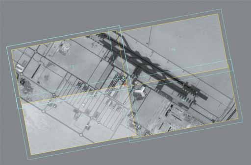
Fig. 6 — Al Maktoum Airport (Dubai, UAE)

Fig. 7 — Shenyang (China)
Table 5 — Primary control of produced products in projects "Al Maktoum Airport" and "Shenyang"
|
Project Name |
Al Maktoum Airport |
Shenyang |
||||
|
|
Ex (m) |
Ey (m) |
Exy (m) |
Ex (m) |
Ey (m) |
Exy (m) |
|
RMS |
1.12 |
0.82 |
1.38 |
1.15 |
1.33 |
1.76 |
|
Mean Module |
0.87 |
0.66 |
1.16 |
0.92 |
1.11 |
1.60 |
|
Maximum "+" |
1.88 |
1.24 |
4.14 |
1.71 |
2.24 |
3.14 |
|
Maximum "-" |
-4.12 |
-3.00 |
- |
-3.12 |
-2.75 |
- |
|
|
RMS |
Mean |
Max |
RMS |
Mean |
Max |
|
Control Points, m |
2.15 |
1.57 |
4.14 |
2.33 |
1.92 |
2.90 |
|
Control Reference, m |
1.22 |
1.07 |
2.17 |
1.74 |
1.50 |
3.14 |
|
Linking Points, m |
1.33 |
1.22 |
2.16 |
- |
- |
- |
Table 6 — Accuracy control of mosaic construction along the cut line in the "Al Maktoum Airport" project
|
Project Name |
Al Maktoum Airport |
||
|
|
Ex (m) |
Ey (m) |
Exy (m) |
|
RMS |
2.057 |
2.525 |
3.256 |
|
Mean Module |
1.550 |
1.973 |
2.686 |
|
Maximum "+" |
5.649 |
6.106 |
8.318 |
|
Maximum "-" |
-4.600 |
-4.600 |
- |
Table 7 Secondary control of produced products in projects "Al Maktoum Airport" and "Shenyang"
|
Project Name |
Al Maktoum Airport |
Shenyang |
|
Exy (m) |
Exy (m) |
|
|
RMS Deviation |
1.38 |
1.76 |
|
Mean Deviation |
1.16 |
1.60 |
|
Maximum Deviation |
4.14 |
3.14 |
As subsequent practice has shown, this method of processing in terms of accuracy for images from spacecraft does not yield to the RPC-polynomial method, but its drawback (the need to use a large number of control points) makes it practically useful only for creating orthophotos over small areas.
Project "Pyatigorsk Polygon"
The "Pyatigorsk Polygon" project considered the possibility of using RPC for refining the georeferencing of video data.
Summary information, results of alignment, accuracy control of the released orthophoto, control of accuracy along the cut lines, and secondary control of the orthophoto-transformed image are presented in tables 8-13, respectively. Table 14 shows the result of aligning video data without using control points.
In Figure 8, microframes of the processed image are shown. Figure 9 reflects the digital height matrix SRTM used in creating the orthophoto-transformed image with a step of 80.5 meters.
Photogrammetric processing was carried out, as in the projects described above, using the PHOTOMOD5.2 software suite. The processing technology was chosen similar to previous projects, except that alignment was performed using RPC.

Fig. 8 — Fragment of the Pyatigorsk Photogrammetric Polygon

Fig. 9 — Digital elevation matrix (SRTM) of the Pyatigorsk Photogrammetric Polygon area
Table 8 Alignment of video data in the "Pyatigorsk Polygon" project
|
Received from spacecraft |
"Canopus-V" |
|
Number of processed video units |
20 microframes |
|
Number of tie points |
126 |
|
Number of control points |
8 |
|
Number of ground control points |
50 |
|
Total points |
184 |
|
Ground control points |
Exy (m) |
|
RMS |
2.33 |
|
Mean |
2.03 |
|
Maximum |
3.78 |
|
Control points |
Exy (m) |
|
RMS |
2.43 |
|
Mean |
2.31 |
|
Maximum |
3.55 |
|
Tie points |
Exy (m) |
|
RMS |
0.61 |
|
Mean |
0.57 |
|
Maximum |
0.96 |
Table 9 Results of video data alignment with one ground control point in the "Pyatigorsk Polygon" project
|
Ground control point |
Exy (m) |
|
RMS |
8.54 |
|
Control points |
Exy (m) |
|
RMS |
7.27 |
|
Mean |
7.09 |
|
Maximum |
9.82 |
|
Tie points |
Exy (m) |
|
RMS |
2.19 |
|
Mean |
2.09 |
|
Maximum |
3.11 |
The tables show the results of alignment, accuracy control of the released orthophoto, control of accuracy along the cut lines, and the secondary control of the orthophoto-transformed image with a spatial resolution of 80.5 m (SRTM matrix).
Project "Columbia"
In the "Columbia" project, an enhanced version of RPC was used, and its distinctive feature was the accuracy control of the produced products using both Google satellite maps and orthophoto plans created by USSG (U.S. Geological Survey) from aerial photography results, freely provided by "Earthexplorer". The orthophoto plans used comply with FGDC-STD-007.3-1998 NSSDA (National Standard for Spatial Data Accuracy) for a scale of 1:4800, with a planar standard deviation (SD) of 1.22 meters. They are supplied in the NAD83/Mississippi coordinate system and, consequently, coordinates of recognized contours were extracted from these orthophoto plans and converted into the WGS84 UTM16N coordinate system.
As in previous cases, photogrammetric processing was carried out at the Center for Earth Remote Sensing (CERS) using "PHOTOMOD5.2". Summary information, results of alignment with reference points (using one reference point, five reference points, and without reference points), is presented in Tables 15-18. Figures 10-12 depict the scheme of processed microframes in this area, the scheme of automatically recognized tie points, and the scheme of aligned microframes, respectively. Primary and secondary quality control, as well as control along the cut line of orthophoto-transformed images, are presented in Tables 19-21.
Table 22 provides estimates of planimetric coordinate discrepancies between two control layers. Figure 13 shows the overall view of the constructed orthophoto plan.

Fig. 10 Scheme of processed microframes in the "Columbia" project

Fig. 11 Scheme of automatically recognized tie points in the "Columbia" project
Table 15 Alignment of video data in the "Columbia" project using one reference point
|
Acquired from the spacecraft |
"Canopus-V" |
|
Number of processed video data units |
70 microframes |
|
Number of tie points |
639 |
|
Number of control points |
6 |
|
Number of reference points |
27 |
|
Total points |
672 |
|
Reference points |
Exy (m) |
|
RMS (Root Mean Square) |
2.25 |
|
Average |
2.06 |
|
Maximum |
3.89 |
|
Control points |
Exy (m) |
|
RMS (Root Mean Square) |
2.53 |
|
Average |
2.24 |
|
Maximum |
3.94 |
|
Tie points |
Exy (m) |
|
RMS (Root Mean Square) |
0.44 |
|
Average |
0.38 |
|
Maximum |
1.45 |
Table 16 Alignment results of video data using 1 reference point in the "Columbia" project.
|
Reference point |
Exy (m) |
|
RMS (Root Mean Square) |
0.46 |
|
Control points |
Exy (m) |
|
RMS (Root Mean Square) |
1.07 |
|
Tie points |
Exy (m) |
|
RMS (Root Mean Square) |
0.29 |
Table 17 Alignment results of video data without reference points in the "Columbia" project.

Fig. 12 Scheme of aligned microframes in the "Columbia" project.
Quality control was carried out at the CERS (Center for Earth Remote Sensing). The most important results are presented in Tables 19, 20, and 21.
Table 22 shows the comparison of planimetric coordinate discrepancies between two control layers.
Figure 13 shows the overall view of the constructed orthophoto plan.
Table 20 Accuracy control of mosaic construction along cut lines in the "Pyatigorskiy Poligon" project
|
|
Ex (m) |
Ey (m) |
Exy (m) |
|
RMS |
1.000 |
1.057 |
1.455 |
|
Mean modulus |
0.794 |
0.850 |
1.269 |
|
Maximum "+" |
2.149 |
2.145 |
2.829 |
|
Maximum "−" |
-2.140 |
-2.154 |
- |
Table 21 Secondary control of produced products in the "Columbia" project.
|
Discrepancies |
Control of output products according to Earthexplorer orthophotoplanes |
Control of orthophotoplanes according to "Google" satellite maps |
|
In plan |
Exy (m) |
Exy (m) |
|
RMS |
2.35 |
4.49 |
|
Mean |
2.21 |
4.28 |
|
Maximum |
3.90 |
6.00 |
Table 22 Evaluation of discrepancies in the positions of orthophotoplan points obtained from the "Earthexplorer" information resource and recognized on "Google" satellite map.
|
In plan |
Exy (m) |
|
RMS |
3.12 |
|
Mean |
2.87 |
|
Maximum |
4.90 |
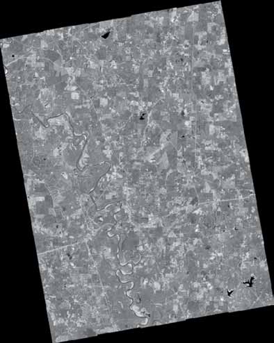
Figure 13 Output of the "Columbia" project.
During the project, it was noted that:
- RPC polynomials exhibit systematic errors (root mean square error at control points using digital terrain model is 17.74 meters, root mean square error at control points using mean terrain height is 17.86 meters), which can be compensated by using ground control points;
- Using at least one ground control point significantly reduces systematic errors (root mean square error at control points is 3.04 meters);
- The set of tie points during product production was done automatically and, as practice showed, did not significantly require manual filtering or addition of tie points.
When creating orthophotoplan, in accordance with the photogrammetric work instruction, the alignment accuracy corresponds to the plan coordinates alignment accuracy of ground control points for creating maps of scales 1:10,000 and larger, and the accuracy of created digital orthophotoplans met the requirements for geometric accuracy of topographic maps of scales 1:10,000 and larger.
Project "Warsaw"
Development of orthotransformed products using microframes of "Canopus-V" was implemented in the software module "ERDAS IMAGINE LPS". The complexity of developing this technology in this software product was the fact that until recently it did not support RPC alignment provided with "Canopus-V" and BKA satellite images. As a result of trilateral cooperation between "Innoter", FGUP "NPP VNIIEM", and Integraph, this problem was overcome.
As a result of work on the "Warsaw" project, which was executed precisely in the "ERDAS IMAGINE LPS" software module, an orthophotoplan of an urban development area was created. This involved the collection of tie points, identification of control and ground control points, alignment of microframes using RPC, digital height matrix (SRTM), ground control points, and tie points with subsequent automatic mosaic stitching into an orthotransformed image. Figure 14 shows the microframes used for stitching in the project. Figures 15-16 depict the alignment windows of the microframe block of the "Warsaw" project using RPC in LPS and automatic mosaic construction of orthophotoplan, as well as the resulting output product respectively. Tables 23-24 reflect the project results. Figure 17 presents a sample of the output product.

Figure 14 Microframes used for stitching in the "Warsaw" project

Figure 15 Alignment window of the microframe block of the "Warsaw" project using RPC in LPS

Figure 16 Automatic mosaic construction window of orthophotoplan in LPS
Table 23 Results of alignment in the "Warsaw" project
|
Obtained from spacecraft |
"Canopus-V" |
|
Number of processed video data units |
4 microframes |
|
Ground control points |
Exy (m) |
|
Root mean square |
2.57 |
|
Average |
2.31 |
|
Maximum |
3.97 |
|
Control points |
Exy (m) |
|
Root mean square |
2.76 |
|
Average |
2.54 |
|
Maximum |
3.89 |
|
Tie points |
Exy (m) |
|
Root mean square |
0.74 |
|
Average |
0.70 |
|
Maximum |
1.45 |
Table 24 Results of independent orthophotoplan control for Warsaw city area using "PHOTOMOD5.2"
|
In plan |
Exy (m) |
|
Root mean square |
4.89 |
|
Average |
4.28 |
|
Maximum |
7.93 |
|
In height |
Exy (m) |
|
Root mean square |
2.42 |
|
Average |
2.10 |
|
Maximum |
3.61 |
Figure 17 Sample of the orthophotoplan output product for the Warsaw city area
Results from the project showed that the microframes were aligned with the ground control points with sufficient accuracy for the creation of the orthophotoplan at the required scales. The root mean square errors for both the plan and height were within acceptable limits for topographic mapping purposes.
Results of "Kazan" Project
While creating an orthophotoplan, a software module is also included in the "ERDAS IMAGINE LPS" software, a module that allows one to create orthophotoplans using microframes from the "Canopus-V" satellite. In this module, as well as in the "Warsaw" project, all stages were implemented in strict accordance with the photogrammetric work instruction, including the collection of tie points, the identification of control and ground control points, alignment of microframes using RPC, digital elevation matrix (SRTM), ground control points, and tie points with subsequent automatic mosaic stitching into an orthotransformed image. Figure 18 shows the microframes used for stitching in the "Kazan" project. Figures 19-20 depict the alignment windows of the microframe block of the "Kazan" project using RPC in LPS and automatic mosaic construction of orthophotoplan, as well as the resulting output product, respectively. Tables 25-26 reflect the project results. Figure 21 presents a sample of the output product.

Figure 18 Microframes used for stitching in the "Kazan" project

Figure 19 Alignment window of the microframe block of the "Kazan" project using RPC in LPS

Figure 20 Automatic mosaic construction window of orthophotoplan in LPS
Table 25 Results of alignment in the "Kazan" project
|
In plan |
Exy (m) |
|
Root mean square |
4.34 |
|
Average |
3.92 |
|
Maximum |
7.17 |
|
In height |
Exy (m) |
|
Root mean square |
2.88 |
|
Average |
2.43 |
|
Maximum |
4.38 |
Table 26 Results of independent orthophotoplan control for the Kazan city area using "PHOTOMOD5.2"
|
In plan |
Exy (m) |
|
Root mean square |
4.14 |
|
Average |
3.72 |
|
Maximum |
6.23 |
|
In height |
Exy (m) |
|
Root mean square |
2.71 |
|
Average |
2.33 |
|
Maximum |
4.09 |
Figure 21 Output product sample for the "Kazan" city area
Conclusion
Creating orthophotoplans from satellite imagery is a complex process that involves multiple stages and technologies, such as digital elevation models, ground control points, and highly precise software for alignment and image processing. The projects in Warsaw and Kazan outlined above demonstrate the successful application of these techniques to produce high-quality, accurate orthophotoplans suitable for urban planning, land use management, and other applications that require precise, reliable mapping data.
The results of the Warsaw and Kazan projects show that the orthophotoplans created were accurate, with root mean square errors in plan and height within acceptable limits for topographic mapping purposes. The combination of microframe stitching, automatic alignment, and rigorous quality control procedures ensures that the orthophotoplans meet the required standards of precision and reliability.
These projects highlight the importance of integrating advanced photogrammetric techniques with satellite imagery to generate precise mapping products essential for modern urban planning and land management tasks. As satellite technology and software capabilities continue to evolve, the quality and accuracy of orthophotoplans are expected to further improve, supporting more sophisticated and demanding applications in various fields.
It is anticipated that the methods and technologies discussed in this paper will contribute to the advancement of remote sensing and geospatial analysis, providing decision-makers with the data they need to make informed choices about urban development and environmental management.
This research is supported by the Russian Foundation for Basic Research (Project No. 22-01-2022) and the State Assignments of the Government of the Russian Federation (Project No. 22-02-2023).
As a result of photogrammetric processing in the LPS software module, a mosaic image from microframes of the "Canopus-V" spacecraft images was created, which, in terms of its accuracy characteristics, is not inferior to orthophotoplans constructed in "PHOTOMOD5.2".
Conclusions
Based on the accuracy characteristics obtained, the following conclusions were drawn:
- The materials obtained from the "Canopus-V" and Belarusian spacecraft are suitable in terms of their accuracy characteristics for creating and updating topographic and navigational maps and orthophotoplans at scales of 1:25000 and larger. Although the accuracy characteristics meet the requirements for creating or updating maps larger than 1:25000, the decoding characteristics of the materials allow cartographic work only for maps of scale 1:25000 and smaller.
- Based on the obtained estimates of the adjustment of materials from space images with the "Canopus-V" spacecraft, a systematic georeferencing error of microframes was identified, with an average value of 17.83 meters. Similar values to this systematic error were obtained by other organizations that evaluated the accuracy characteristics of the "Canopus-V" spacecraft.
- The identified systematic georeferencing error can be eliminated by calculating more accurate RPCs, and therefore further improvement in the accuracy characteristics of materials obtained from this satellite remains possible.
Based on the conducted research, an expert opinion of LLC "Innoter" was developed, presented for the evaluation of flight test results.
References Used
- Vladimirov, A.V. Space system for operational monitoring of man-made and natural emergencies based on the Canopus-V spacecraft and the Belarusian Space Apparatus / A.V. Vladimirov, R.S. Salikhov, N.A. Senik, S.A. Zolotoy // Issues of Electromechanics. VNIIEEM Proceedings. - 2008 - Vol. 105. - P.49-57
- Makusheva, E.V. Development of a dynamic geometric model of shooting optical-electronic shooting systems for prospective space complexes like "CANOPUS-V" / E.V. Makusheva, V.V. Nekrasov // Issues of Electromechanics. VNIIEEM Proceedings. - 2010 - Vol. 119. - P.25-30
- Kravtsova, E.V. Technology for processing images from the prospective "Canopus-V" satellite using PHOTOMOD / E.V. Kravtsova. - 2011 - No. 4. - P.33-37
- Ilyin, G.V. Analysis of the possibility of creating topographic plans based on space images for engineering surveys for construction / G.V. Ilyin, V.N. Lavrov, Yurchenko B.A. // - 2012 - No. 1. - P. 97-106
- "Instructions for photogrammetric work in the creation of digital topographic maps and plans", GKINP (GNTA) - 02-036-02. - Moscow: TsNIIGAiK, 2004.
FInoshin D.G., Kravtsova E.V., Lobanov V.K., "Innoter"
Sat-Sun: Non-working days