of geospatial solutions
Sat-Sun: Non-working days
In Russia, there is a shortage of operational land remote sensing data. Therefore, launching the Kanopus-V satellite will allow users to address the following tasks:
- Monitoring of man-made and natural emergencies.
- Mapping.
- Detection of forest fire hotspots, major releases of pollutants into the environment.
- Registration of anomalous phenomena to study the possibility of earthquake prediction.
- Monitoring of agricultural activities, water, and coastal resources.
- Land use.
- Highly cooperative observation of specified areas of the Earth's surface.
To solve these tasks, it is necessary to ensure the prompt creation of orthophotoplanes. The company “Innoter” has developed a technology for processing images in the CFS “Photomod” taking into account the features of the Kanopus-V satellite.
The satellite launch is scheduled for December 2011 from the Baikonur Cosmodrome. It will be placed in a sun-synchronous orbit at an altitude of 510 km. This orbit was chosen to obtain images with optimal illumination and detailed resolution. The satellite imaging scheme is shown in Figure 1.
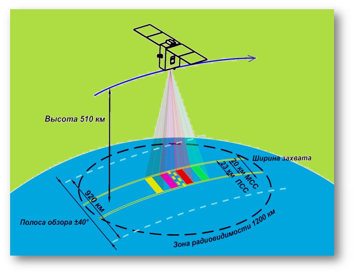
Fig. 1 Kanopus-V satellite imaging scheme
Due to its wide angle of view, the satellite's swath width is 920 km. With these orbit parameters, the radio visibility zone will cover 1200 km. The main characteristics of the satellite are presented in Table 1.
Table 1. Main characteristics of the Kanopus-V satellite
|
Satellite size, m×m |
0.9×0.75 |
|
Satellite mass |
450 kg |
|
Payload mass, kg |
110 |
|
Orbit: altitude, km inclination, deg orbital period, min equator crossing time, hrs |
Sun-synchronous morning 510 98 94.74 10:30 – 11:00 |
|
Platform: |
from -40° to 40° 5 0.001 |
|
Repeat observation period, days |
15 |
|
Average daily power, W |
300 |
|
Active lifespan, years |
5-7 |
The satellite is equipped with:
- target equipment complex (TEC);
- onboard information system (OIS);
- radio information transmission channel (RITC);
- service platform.
The OIS includes a battery-backed onboard storage device (OSD) with a capacity of 2x24GB, providing both storage of video information for at least 5 days and buffering it for direct transmission via the RITC channel. The main characteristics of the RITC are presented in Table 2.
Table 2. Main characteristics of the RITC
In Russia, there is a lack of real-time remote sensing data. Therefore, launching the Canopus-V satellite will enable users to address the following tasks:
- Monitoring of man-made and natural emergencies.
- Cartography.
- Detection of forest fire hotspots, large emissions of pollutants into the environment.
- Recording anomalous phenomena to study the possibility of earthquake prediction.
- Monitoring of agricultural activities, water, and coastal resources.
- Land use.
- High-resolution observation of specified areas of the Earth's surface.
To solve these tasks, it is necessary to ensure the prompt creation of orthophotomaps. The company "Innother" has developed a technology for processing images in CFS "Photomod", taking into account the features of the Canopus-V satellite.
The satellite launch is planned for December 2011 from the Baikonur Cosmodrome. It will be placed into a sun-synchronous orbit at an altitude of 510 km. This orbit was chosen to obtain images with optimal illumination and detail. The satellite's imaging scheme is shown in Figure 1.
Fig.1 Canopus-V Satellite Imaging Scheme
Thanks to its wide swath angles, the satellite's coverage area is 920 km. With these orbit parameters, the radio visibility zone will be 1200 km. The main characteristics of the satellite are presented in Table 1.
Table 1. Main Characteristics of Canopus-V Satellite
|
Satellite Size, m×m |
0.9×0.75 |
|
Satellite Mass |
450 kg |
|
Payload Mass, kg |
110 |
|
Orbit: altitude, km inclination, deg orbital period, min crossing time at the equator, hour |
Sun-synchronous morning 510 98 94.74 10:30 – 11:00 |
|
Platform: |
from -40° to 40° 5 0.001 |
|
Repeat Observation Period, days |
15 |
|
Average Daily Power, W |
300 |
|
Active Service Life, years |
5-7 |
Onboard the satellite are:
- Target Equipment Complex (TEC);
- Onboard Information System (OIS);
- Radio Link for Information Transmission (RLIT);
- Service platform.
OIS includes an energy-independent onboard memory device (OMD) with a capacity of 2x24GB, providing both video information storage for at least 5 days and buffering for direct transmission via RLIT. The main characteristics of RLIT are presented in Table 2.
Table 2. Main Characteristics of RLIT
|
Operating Frequency Range, MHz |
8048 - 8381.5 |
|
Number of Transmission Channels |
2 |
|
Data Transmission Rate, Mbit/s |
61.4…122.88 |
TEC includes two imaging systems:
- Panchromatic Imaging System (PIS);
- Multispectral Imaging System (MIS) provides image acquisition in four spectral zones.
Imaging can be conducted simultaneously in panchromatic and multispectral modes, as well as in various combinations of individual spectral zones, up to imaging in one spectral zone. The main characteristics of PIS and MIS are presented in Table 3.
Table 3. Main Characteristics of PIS and MIS
|
Main Characteristics |
PIS |
MIS |
|
Number of Spectral Channels |
1 |
4 |
|
Spectral Ranges (at 0.5 level), μm |
Panchromatic (0.52 – 0.85) |
Blue (0.54-0.6) |
|
Focal Length, mm |
1797.5 |
359.5 |
|
Relative Aperture |
1:10.3 |
1:5.6 |
|
Light Transmission |
0.7 |
0.6 – 0.8 |
|
Matrix Size (pixels) |
1920x985 |
1920x985 |
|
When Shooting Nadir: Capture Bandwidth, km Geometric Resolution, m Linear Resolution on the Ground in Fair Conditions, m |
23.3 2.1 2.7 |
20.1 10.5 12 |
|
Area Simultaneously Captured, km |
45.3 (6 frame fragments) |
195 |
The projection of MIS and PIS images on the Earth is shown in Figure 2.
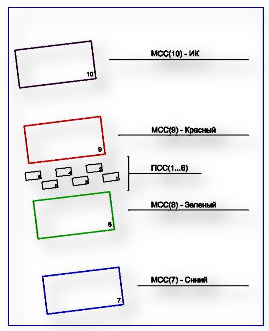
Fig.2. Projection of MIS and PIS Images on Earth
When developing the image processing technology for the "Canopus-V" spacecraft by "Innother", the peculiarities of the spacecraft's imaging system (KCA) were maximally taken into account. Model images (MI) based on the geometric model of the imaging system were created for this purpose. Accuracy assessments of the created orthophotoplan were conducted considering both the maximum possible precision and the errors introduced by the navigation system.
These tasks were addressed through modeling of the imaging routes of the "Canopus-V" spacecraft. To create MI, an image from the Resurs-DK satellite over the territory of an experimental test range with elevation differences reaching 400m was utilized. Ground control points for construction, measured with decimeter accuracy (sigma = 0.2m), were taken from the test range, totaling 180 points. Using the Resurs-DK image and digital elevation model (DEM) data from SRTM (Shuttle Radar Topographic Mission), an orthophotoplan was constructed with a pixel size of 1m and root mean square transformation accuracy (RMS) of 2.11m. The orthophotoplan built using the Orthomap software served as the basis for creating model images of the "Canopus-V" spacecraft. The actual creation of MI and calculation of rational polynomial coefficients (RPC) were performed using the "Neogeosat" software package. MI were created considering errors introduced by the navigation system, thus simulating conditions close to reality.
Only images from the panchromatic camera were used for the project. As the CCD matrices do not overlap, eight routes were generated from MI to ensure complete coverage of the test area, with images shifting as the satellite moved along its orbit. Figure 3 depicts routes from model images of the panchromatic camera.

Fig.3 Routes from model images of the panchromatic camera
Orthophotoplans were created at various stages of leveling, and accuracy analyses of the resulting orthophotos were conducted. To build orthophotoplans, the following were used:
- Model images with a resolution of 2m;
- Ground control points, totaling 170 points;
- DEM based on SRTM data.
Connecting points were placed automatically in leveling the image block, with autocorrelation control.
External orientation of the image blocks was carried out using metadata (RPC) and ground control points, ranging from 1 to 160. Orientation accuracy was evaluated using 10 checkpoints. The leveling results (see Figure 5) showed that adding a small number of points significantly increased accuracy by compensating for systematic errors. Further increasing the number of control points led to a gradual increase in accuracy.
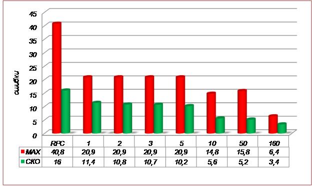
Fig.4 Accuracy assessment of leveling
Orthophotoplans were created following the leveling of route surveys using 160 control points. SRTM data was used as the DEM for creating orthophotoplans. The accuracy of this elevation matrix is estimated at 20m and can lead to positional displacement (RMS) of 17m. Transformation areas for mosaic creation were automatically generated. The pixel size of the orthophotoplan was set at 2m.
Initial orthophotoplan control was performed using all available project points and along cut lines. Accuracy control results for ideal and real shooting scenarios are presented in Table 4.
Table 4. Mosaic accuracy control
|
Mosaic accuracy control |
by control and validation points (m) |
along cut lines (m) |
|
MAX |
12.8 |
5.0 |
|
RMS |
3.4 |
2.6 |
Accuracy of the resulting orthophotoplans using this technology was also assessed using independent control points: maximum discrepancies (MAX) reached 5.53m, RMS was 3.37m.
Conclusions
The application of Photomod for processing Canopus-V spacecraft images allows for fully automatic measurement of tie points for block leveling. Additionally, transformation areas for mosaic creation are automatically generated. This has increased data processing speed and maximally automated the process.
According to the photogrammetric work instructions [2]:
Leveling accuracy corresponds to the planimetric coordinate leveling accuracy of control points for creating maps at a scale of 1:25000.
- Accuracy of mosaic creation along cut lines meets the instruction's accuracy requirements up to a scale of 1:5000.
- Accuracy of created digital orthophotoplans satisfies the requirements for geometric accuracy of topographic maps at a scale of 1:25000.
- The obtained results recommend the use of Canopus images for cartographic purposes within a scale range of 1:10000 and finer.
References
[1] - Journal of FGUP "NPP VNIIEM" - "Questions of Electromechanics" Vol. 105 2008
[2] - Instructions for photogrammetric work in the creation of digital
topographic maps and plans, GKNP (GNTA) -02-036-02
Elena Vladimirovna Kravtsova, "Innother"
Sat-Sun: Non-working days