of geospatial solutions
Sat-Sun: Non-working days
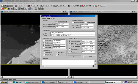
Source Data
As part of the International experiment “HRS Study Team”, the company “Innoter” provided a stereoscopic pair of HRS (SPOT-5) images for test site No. 9 (Bavaria), along with its metadata file, fragments of test DEMs, coordinates of 81 GPS points, and field sketches of their locations. The geodetic coordinates of DEMs and GPS points are provided in zone 4 of the Gauss-Kruger projection, on the Bessel ellipsoid with Potsdam datum. The image acquisition date is October 1, 2002. Table 1 presents the coordinates of the corners of the left and right images.
Service information on CD-ROM (for each image):
- METADATA.
- ICON.JPG
- STYLE.XSL
- DIM PREVIEW.JPG
- IMAGERY.TIF
Orientation angles:
- Orientation angle: 15° 08' 41."7948
- Incidence angle: 23° 01' 43."2696
Table 1.
|
Left |
Image Coordinates (pxl) |
|||
|
1. |
B = 48° 20' 31" N |
L = 11° 59' 17" E |
1 |
1 |
|
2. |
B = 48° 03' 24" N |
L = 13° 32' 48" E |
12 000 |
1 |
|
3. |
B = 47° 32' 16" N |
L = 13° 19' 19" E |
12 000 |
12 000 |
|
4. |
B = 47° 49' 16" N |
L = 11° 46' 42" E |
1 |
12 000 |
|
Right |
Image Coordinates (pxl) |
|||
|
1. |
B = 48° 21' 00" N |
L = 11° 58' 47" E |
1 |
1 |
|
2. |
B = 48° 03' 09" N |
L = 13° 32' 00" E |
12 000 |
1 |
|
3. |
B = 47° 31' 58" N |
L = 13° 18' 30" E |
12 000 |
12 000 |
|
4. |
B = 47° 49' 42" N |
L = 11° 46' 11" E |
1 |
12 000 |
Source stereo images were obtained using the along-track scanning method along the flight direction. During the terrain survey, their geometry was formed by incrementally building the frame with individual rows, each projected onto the focal plane at the same optical axis tilt angle: approximately 23° for the left image along the stereo pair baseline and approximately 22.5° in the opposite direction for the right image. The slant angle is about 15°. The ratio B/H for this stereo pair is approximately 0.72. Each row of the original images is a central projection of a narrow strip of terrain. Its width is determined by a scanning aperture of d = 10 m (on the ground).
Thus, from the perspective of projective geometry, the SPOT-5 scanner images represent a combination of oblique parallel and central projections.
Although SPOT-5 stereoscopic images have geometric properties somewhat different from those of images with central projection, Innoter considers it expedient to explore the possibility of creating a DEM using the "Z-Space" photogrammetric system.
Preliminary Processing Results
Analysis of the acquired source materials allowed the following findings. HRS images (SPOT-5) are compressed along the "X" axis and rotated 90° clockwise.
The dynamic range of image densities is sufficiently wide, allowing avoidance of histogram adjustment during processing.
For photogrammetric processing of HRS (SPOT-5) stereo images in version 2.0 of the "Z – Space" system, it is necessary to determine the scanner's calibration parameters. These parameters are used for the correct processing of images using the mathematical model of the HRS scanner.
Since the "Z – Space" system uses the WGS-84/UTM coordinate system as the working geodetic coordinate system, coordinates of GPS points were initially transformed from the original (Gauss-Krüger projection, Bessel ellipsoid with Potsdam datum) into the working coordinate system.
To find the original GPS points on SPOT-5 images, researchers were provided with their field outlines in graphic form.
However, direct identification of GPS points on the images through their outlines is a complex task in practice, as these outlines are overly simplified representations of terrain objects. Therefore, the decision was made to first construct an approximate terrain model based on Russian topographic maps and use it to locate GPS points by their geodetic coordinates. As a result, 14 tie points were identified and measured on the presented stereo pair, which were used for mutual orientation of the stereo pair.
Table 2.
|
№№ Point |
Left Image |
Right Image |
||
X, pxl |
Y, pxl |
X, pxl |
Y, pxl |
|
1 |
48 |
77 |
101 |
164 |
2 |
545 |
11853 |
310 |
11937 |
3 |
11017 |
10547 |
10781 |
10632 |
4 |
11090 |
2330 |
11039 |
2416 |
5 |
5697 |
5569 |
5548 |
5656 |
6 |
219 |
7337 |
58 |
7422 |
7 |
11403 |
5906 |
11181 |
5992 |
8 |
5424 |
493 |
5430 |
578 |
9 |
4797 |
8104 |
4794 |
8102 |
10 |
8363 |
5260 |
8333 |
5276 |
11 |
5914 |
4190 |
5966 |
4210 |
12 |
2425 |
6315 |
2355 |
6299 |
13 |
6138 |
9193 |
6163 |
9248 |
14 |
7607 |
1407 |
7574 |
1420 |
Internal Image Orientation
Before starting the internal orientation process, both images were rotated counterclockwise by 90°. The original "file" flat image coordinate system HRS (SPOT-5) is "left-handed" and looks as follows:
This coordinate system OХУ has its origin in the upper left corner of the image. The transformed coordinate system O’X’Y’ is "right-handed". The dimensions along the X' and Y' axes are in micrometers.
The coordinate transformation from system OХУ to system O'X'Y' was performed using the dependencies provided below.
X' mkm = Xpxl  x  dmkm/pxl
Y' mkm = (-Ypxl) x d mkm/pxl
d = 6.8 mkm
Based on this data, the mutual orientation of the scanner images of the stereo pair was performed.
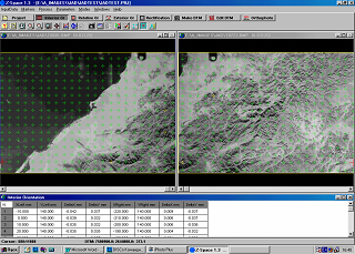
Mutual Orientation of Images
To perform the mutual orientation of this stereo pair, 14 tie points located in the image overlap area were used. Pixel coordinates of these points are listed in Table 2 above.
The coordinates of these points were transformed using the dependencies provided above. Transformed coordinates X’ and Y’ for each image are listed in Table 3.
Table 3.
|
№№ Point |
Image Left |
Image Right |
||
|
X, mkm |
Y, mkm |
X, mkm |
Y, mkm |
|
|
1 |
312 |
38499.5 |
656.5 |
37934 |
|
2 |
3542.5 |
-38044.5 |
2015 |
-38590.5 |
|
3 |
71610.5 |
-29555.5 |
70076.5 |
-30108 |
|
4 |
72085 |
23855 |
71753.5 |
23296 |
|
5 |
37030.5 |
2801.5 |
36062 |
2236 |
|
6 |
1423.5 |
-8690.5 |
377 |
-9243 |
|
7 |
74119.5 |
611 |
72676.5 |
52 |
|
8 |
35256 |
35795.5 |
35295 |
35243 |
|
9 |
31180.5 |
-13676 |
30004 |
-14228.5 |
|
10 |
11680.5 |
19103.5 |
11329.5 |
18544.5 |
|
11 |
7592 |
2171 |
6818.5 |
1618.5 |
|
12 |
51213.5 |
-18902 |
49907 |
-19454.5 |
|
13 |
65214.5 |
21112 |
64798.5 |
20553 |
|
14 |
45591 |
9678.5 |
44811 |
8119.5 |
Based on these data mutual orientation elements of the stereo pair were calculated:
?1 = - 5o10’38.42”  ; ?1 =0o00’00.00”  ; ?1 = - 0o06’10.650”;
?2 = - 5o16’45.52”  ; ?2 =0o03’31.49”  ; ?2 = - 0o06’06.606”;
Iteration number =6.
Residual lateral parallaxes are shown below:
Table 4.
|
|
|
|
|
|
|
|
|
|
|
|
|
|
|
|
|
|
|
|
|
|
|
|
|
|
|
|
|
|
|
|
|
|
|
|
Creation of epipolar images
The results of mutual orientation were used in the process of creating epipolar images of the stereo pair using known strict dependencies.
Below are the transformed coordinate values of the 14 points used in the coordinate system of epipolar images.
Table 5.
|
|
|
|
|
|
|
|
|
|
|
|
|
|
|
|
|
|
|
|
|
|
|
|
|
|
|
|
|
|
|
|
|
|
|
|
|
|
|
|
|
|
|
|
|
|
|
|
|
|
|
|
|
|
Calculating the average square root of the error of determination and height:
X The average standard deviation, mkm = 2.0. Y - an average root-mean-square error mkm = 2.4.
Conclusions
The possibility of conducting and conducting accurate photogrammetric determinations in the air was shown, as evidenced by the low values of the average deviation and mean square root error of the definition.
The possibility of further investigation of the geodetic and technical data using a panoramic camera for photogrammetry, which makes it possible to ensure the possibility of an accurate definition, was shown.
Analysis of ordinates of homonymous tying points by the criterion of their equality to each other showed that the accuracy of creating epipolar images corresponds to the accuracy of mutual orientation of the original images.
External orientation of images
Further, external orientation of the stereo model of the terrain was performed in the geodetic space of the Gauss-Krueger projection on the Krasovsky ellipsoid.
To perform the external orientation process of HRS (SPOT-5) epipolar images, it is necessary to find and reliably identify existing reference points. Typically, GPS information is provided in the form of digital outlines of each point and a general scheme of their mutual arrangement on working areas, executed on aerial photographs or high-resolution satellite images. Unfortunately, the provided GPS point position data in the form of field outlines did not allow their reliable identification not only on images but also on the transferred cartographic materials.
Therefore, Russian-produced cartographic materials were used as additional material.
The combined use of field outlines and Russian-produced cartographic materials allowed for the correct completion of the external orientation process of images and ensured the possibility of creating the required DEM.
Results of stereo model orientation
Geodetic coordinates of the origin of the coordinate system:
B0 = 29° 08' 16.244" L0 = 25° 26' 27.131"
Elements of external orientation of images:
Left: ?1 = - 5° 42' 34.81" ; ?1 = 29° 13' 45.22" ; ?1 = 20° 34' 51.14"
RMSxy = +/- 14.0 m
Right: ?2 = 7° 26' 19.264" ; ?2 = - 4° 48' 19.26" ; ?2 = 20° 32' 41.86"
RMSxy = +/- 12.3 m
The obtained value of RMSxy corresponds to the internal accuracy of the used Russian-produced map.
Results of image orientation on the Bessel 1841 ellipsoid, GK-projection:
Elements of external orientation of images:
Left: ?1 = 5° 47' 32.614" ; ?1 = 29° 10' 41.68" ; ?1 = 20° 38' 17.26"
RMSxy = +/- 11.5 m
Right: ?2 = 5° 21' 24.35" ; ?2 = - 4° 51' 48.22" ; ?2 = 20° 36' 18.81"
RMSxy = +/- 8.3 m
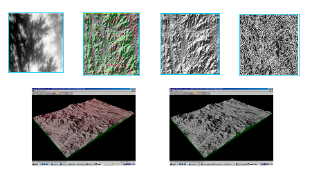
Creation of DEM for the test area Vilsbiburg
Creation of DEM for the test area Vilsbiburg, with coordinates:
UL: R 504000.000 m   H 5374000.000 m
LR: R 554000.000 m   H 5344000.000 m
was performed using profiling method interactively.
The accuracy of this model is characterized by the following parameters:
RMSxy = +/- 9.5 m in plan ; RMSh = +/- 11.8 m in height
The obtained DEM represents the first achieved level of processing stereoscopic data HRS by "Z – Space" system version 2.0.
Conclusion
Research conducted by "Innoter" within the international experiment "HRS Study Team" on test area No. 9 (Baviere) demonstrated the following.
Photogrammetric system "Z-Space" version 2.0, designed for processing images of central projection and adapted for processing scanner images, is suitable for solving the task of creating DEM from HRS stereo images. HRS images possess high geometric and representational properties.
The DEM created by "Innoter" from HRS images using photogrammetric system "Z-Space" version 2.0 for the test area Vilsbiburg (Baviere) has an accuracy of +/- 9.5 m (RMS) in plan and +/- 11.8 m (RMS) in height. With reliable GPS point identification, DEM accuracy can be improved to +/- 8 m in height.
"Innoter" is capable of efficiently processing high-resolution data obtained by HRS system not only in test areas but also in other regions of interest for potential 3D information customers.
Collective "Innoter"
Sat-Sun: Non-working days