Sat-Sun: Non-working days
Customer
Russian Oil Company - Transportation services for petroleum and petroleum products
Project's objective
Creation of a digital terrain model (CMM) and establishment of a 1:5000-scale digital topography plan using space-based stereotyping into the territory of interest, to carry out routine work on submarine crossings of main pipelines and cable lines.
Completed work
- Coating analysis. Data collection according to the survey parameters specified in the technical mission. Starting data. Obtaining space steres, testing and transmission for photogrammetry treatment.
- Photogrammetry processing of space stereosimics. Full photogrammetry cycle with abbreviations and base catalogues in the reference system and WGS84.
Work description
Types of work carried out in the construction of the digital terrain model and the 1:5000 topographic plan using space stereotyping:
- Collect and order space stereotyping that meets TK conditions, control of data obtained;
- Photogrammetry treatment of stereois images using support points from the customer;
- Implementation of terresortization of the terrain.
- Establishment of a TIN model CMR. Exports, converting and reproducing data.
- Creation of a digital orthophotoplane.
- Carrying out the camera decoding of digital orthophoto plans.
- Creation of a digital topography plan, monitoring of work done.
Results
Space stereotyping, TIN Model and Digital Topographic Plan (TPN) of 1:5000 in the AutoCAD system (*.dwg)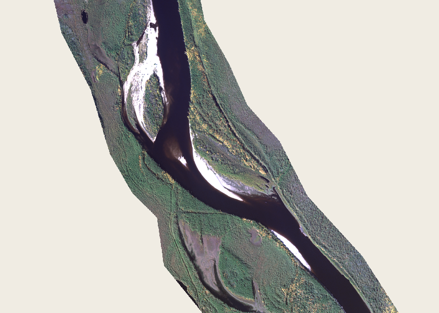
Fragment of orthophotoplan
- The creation of a digital relay and horizontal model was carried out in the stereolymium using analogic and display points.
Structural and regular pickets were installed. The height of the picket and horizontal corresponds to the height of the ground in the Baltic High System. The pickets were horalized. Horizontals have been adjusted in stereolymium (severance of stereoroid altitude) and hydrographic facilities.
- The establishment of the TIN model in the work-coordinate system was carried out by edited horizons (seols) and by pickets. In establishing TIN the surface model, the elements of the hydrographic submarine plan received from the customer were taken into account.
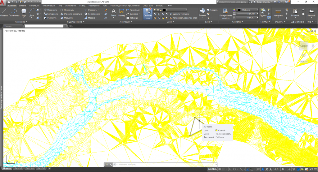
Figure 2 CMR fragment
- Orthophotoplans have been developed using the team sites, the CMR from stereo-processing. The orthophotoplans were divided into a conditional graph, according to the leaflets corresponding to the customer ' s plan, the radiometric correlation of the colour and cut at the boundary of the works took place. Digital topographic plans were transmitted in geotiff format.
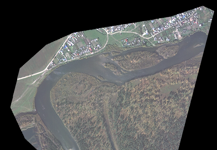
Figure 3 Orthophotoplan fragment
- Cameral decoding of objects was performed on orthophotoplans obtained from photogrammetry processing and monitored the accuracy of objects using team sites and checkpoints. In the course of the Chamber decoding work, the main vectors were identified to create a 1:5000 digital topographic plan. The plan highlighted hydrography facilities; soils, microforms of the ground; road network, roads; utilities and social facilities; electricity and communications; industrial and socio-cultural facilities; vegetation; buildings and buildings; pipelines, etc.
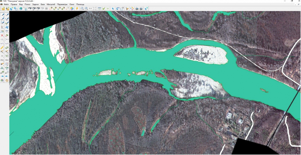
Figure 4 Orthophotographic hydrography
- Orthophotoplan numerical vectors were digitized in Panorama software version 13.0.4, in format *.sxf, using the numerical classifier map5000, in WGS-84. The establishment of a digital topographic plan was carried out in accordance with existing normative documents:
- GCN 02-118 Basic provisions for the development of 1:5000, 1:2000, 1:1000 and 1:500
- ANG 02-127-80 Guidelines for editing of topographic large-scale maps and plans
- GCN 45 Guidelines for Updating Topographic Charts
- Symbols for 1:500-1:5000 topographic plans. M. Nedra, 1989
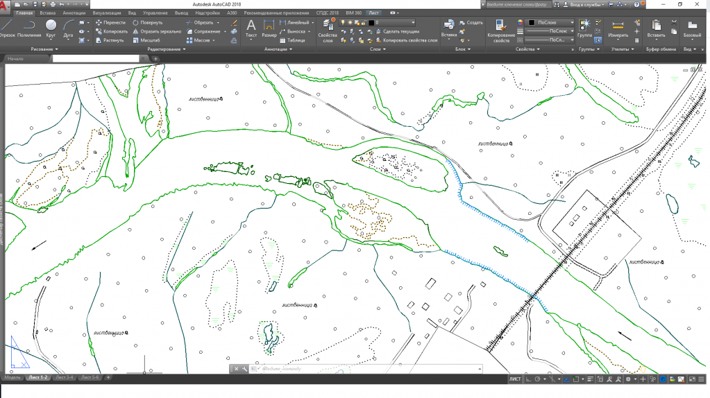
Figure 5 Fragmentation of the final topographic plan 1:5000
As a result of digitization work, several types of quality control of the vector map were performed: topology control, monitoring of the required semantic characteristics, monitoring of the metric position of the objects.
According to the technical mission, the final vector map from the WGS-84 coordinate system has been reproduced and the converted from the format *.sxf to the format *.dwg.
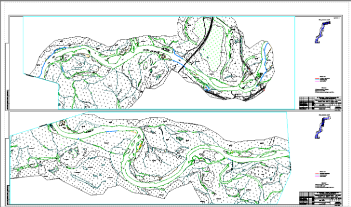
Figure 6 Fragmentation of the M 1:5000 outcome plan, with an outline
Having obtained the digital topographic plan in the conditional coordinate system in format *dwg, the reconciling of the established digital relay model (MTC) and the digital topographic plan (TPC) of 1:5000, with the AutoCAD Civil 3D 2012.

Figure 7 Fragmentation of the combined outcome of the TIN-model and scale 1:5000
Need for consultation?
Fill the form and we will contact you
